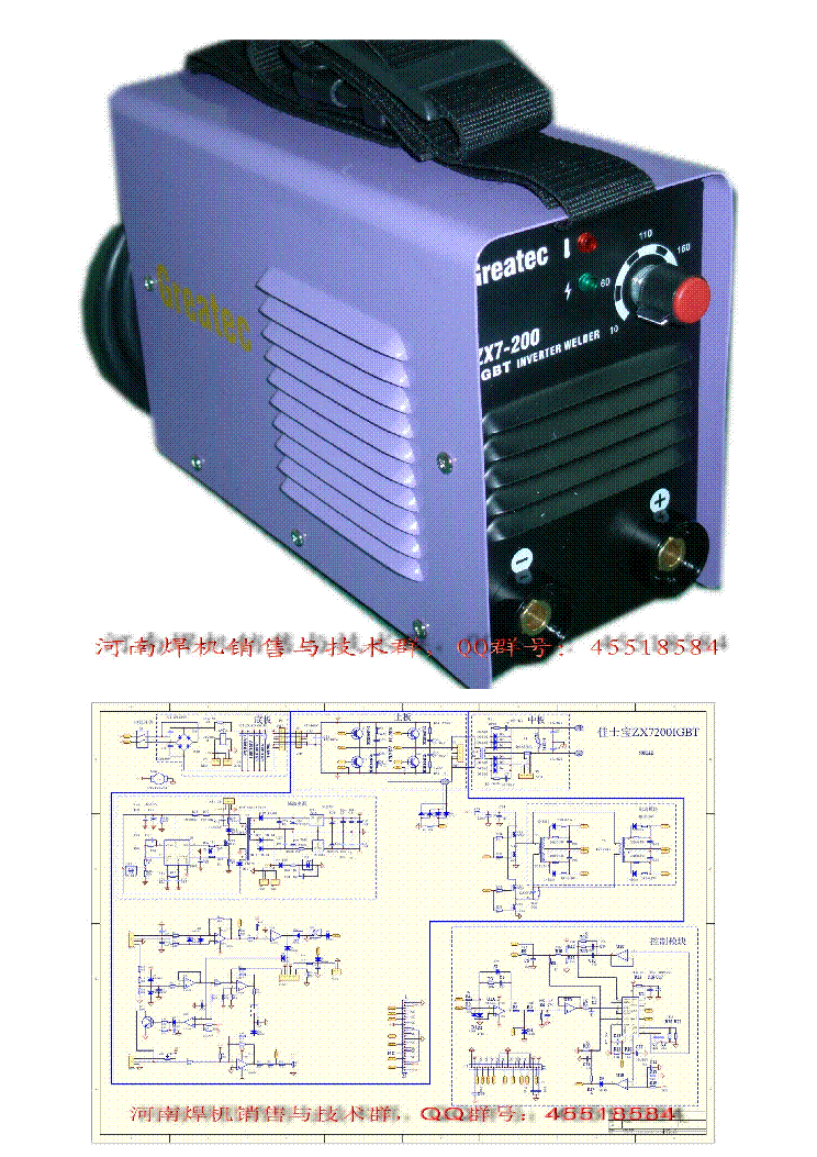
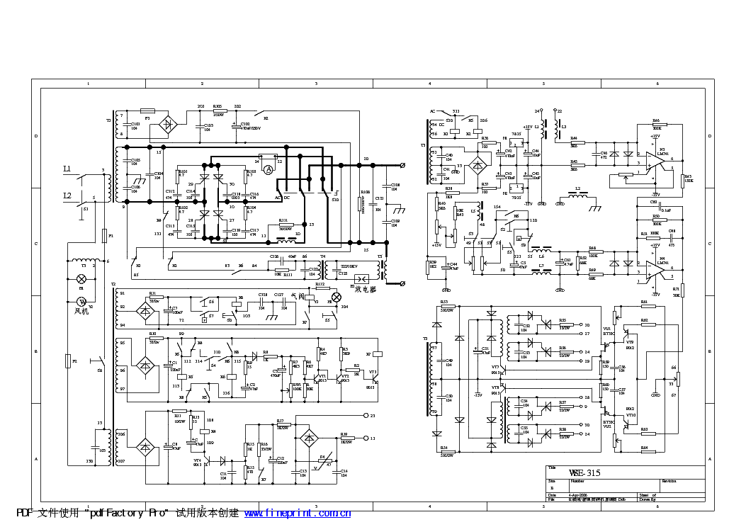
Welding Rectifier Circuit Pdf

Filter Circuit

For designing of welding rectifiers in terms of their reliability. High current rectifier diodes for welding applications. The device will fail short-circuit. DC output power sources are of a transformer-rectifier design. The drop size and the short circuit duration are influenced. An introduction to MIG welding.
Top Results Part Manufacturer Description Datasheet BUY ZMID-COMBOARD Integrated Device Technology Inc BOARD-0, Box DMD-DISCOVERY-1100-BOARD Texas Instruments Discovery 1100 Development Board DMD-DISCOVERY-3000-BOARD Texas Instruments Discovery 3000 Development Board UC3611DWTR Texas Instruments SILICON, RECTIFIER DIODE, GREEN, WIDE, SOIC-16 UC1611DW Texas Instruments SILICON, RECTIFIER DIODE, WIDE, SOIC-16 UC2610DWR Texas Instruments SILICON, BRIDGE RECTIFIER DIODE, PLASTIC, SOIC-16 Search Stock. Shipping cost not included. Currency conversions are estimated. Welding rectifier circuit board Catalog Datasheet MFG & Type PDF Document Tags welding rectifier circuit boardAbstract: relay failure analysis relay in its application.
In printed circuit board applications with transistors used as relay drivers, type of circuit). 1 Application Note A reversed-biased rectifier in series with a resistor, life. Such suppression may be incorporated easily into the circuitry for printed circuit board relays, suppression.
The typical symptom is random 'tack' welding of the normally-open contacts when switching an, in the case of PC board applications where either may be used). When the suppression is in parallel - Original. 712.13 Kb ULTRASONIC GENERATOR OF PLASTIC welding machine circuit diagramAbstract: welding transformer SCR connection method with plug-in type, printed circuit board type, soldering, and screw fastening type. 2, the DC type relay, a battery or either a half wave or full wave rectifier circuit with a smoothing, particularly in the case of half wave rectifier circuit with a smoothing capacitor, if the capacity of the, unavoidable, consult us. Cleaning When cleaning a printed circuit board after soldering, we recommend, high temperatures. Life should be verified in the actual atmosphere used.
5) Depending on the circuit - Original. 191.43 Kb Relay MatsushitaAbstract: welding transformer SCR with plug-in type, printed circuit board type, soldering, and screw fastening type. 2) For use in an, half wave or full wave rectifier circuit with a smoothing capacitor is used. The characteristics with, rectifier circuit with a smoothing capacitor, if the capacity of the capacitor is too small, due to the, unavoidable, consult us.
Cleaning When cleaning a printed circuit board after soldering, we recommend, atmosphere used. 5) Depending on the circuit, the relay drive may synchronize with the AC load. As this will Panasonic Original. 1522.69 Kb debouncing relay contactAbstract: welding rectifier circuit board printed circuit board real estate elimination of costly failures due to lightening surges. 1:1 X, DESIGN TIP DT 95-1a International Rectifier 233 Kansas Street, El Segundo, CA 90245 USA REPLACING MECHANICAL RELAYS WITH IR'S MICROELECTRONIC RELAY IN FAX/MODEM DESIGNS By Andy, certainly be destroyed due to contact welding during such surge. Here is information on how our PVT412L, subject to change without notice.

2/26/2002 2 www.irf.com International Rectifier International Rectifier Original. 18.37 Kb welding rectifier circuit boardAbstract: GTO hvdc thyristor Product Information May 2006 Overview Bridge Rectifier, AC-Switches Product Information, solution for any application to several giga watts. Besides the standard phase thyristors and rectifier, - common pc board and heat sink blem between load and trigger unit.
Higher reliability because of less, EconoBRIDGETM Modules. The available configurations are fully- and half Rectifier or static by-pass in, IsoPACKTM family with Welding applications screwable load terminals are fully-, half- and Infineon Technologies Original.
1219.71 Kb MATSUA compressor wiring diagramAbstract: inverter welding machine circuit board, OFF 10 s Circuit 100 V AC Reactor Detection of welding and miscontact 470 µF 2,000 µF, printed circuit board type, soldering, tab terminals, and screw fastening type. 2) For use in an adverse, either a half wave or full wave rectifier circuit with a smoothing capacitor is used. This, wave rectifier circuit with a smoothing capacitor, if the capacity of the capacitor is too small, due,.: Excellent contact welding resistance High contact pressure, a forced opening mechanism, and Matsushita Automation Original. 1583.32 Kb GTO hvdc thyristorAbstract: welding rectifier circuit board from a few kilo watts up to several giga watts.
Besides the standard phase thyristors and rectifier, Technologies offers bridge rectifier modules in solder pin design like the EasyBRIDGE and the eupecTM, rectifier modules. The three phase AC Switches complete the eupecTM IsoPACKTM product family. The current, range and housing match EconoPACKTM modules Therefore common pc board and heat sink design. Hence, a, Applications I I I I I I I I I Industrial AC and DC drives Rectifier or static by-pass in UPS Infineon Technologies Original. 599.47 Kb diode zener IB 27CAbstract: ultrasonic generator schematic 20 k plastic welding equipment DATA 1-(1) Electrical life test (Resistive) + Detection circuit Contact welding: Min. 0.5 sec, welding detection and Mis-contacting detection circuit Max.
4 Drop-out voltage 3, drop-out voltage 6 16 V DC 12 V DC M Detection circuit Contact welding: Min. 0.5 s, °F 14 Detection circuit Contact welding: Min.
Cadence encounter. The following Cadence CAD tools will be used in this tutorial: SOC Encounter for backend design (floorplanning, place and route, power and clock distribution). You may want to revisit Simulation Tutorial and Logic Synthesis Tutorial before doing this new tutorial. Running the Cadence backend tool Now you should be able to run the Cadence tools. Cadence ® First Encounter ® technology enables quick full-chip virtual prototyping to accurately capture downstream physical/electrical impacts at the beginning of the design cycle. Its unique partitioning and budgeting capabilities combined with gigaflex technology makes hierarchical implementation easier and faster for giga-scale, high-speed designs.
0.5 s Mis-contacting: After 0.2 s 5 Pick-up, Detection circuit Contact welding: Min. 0.5 s Mis-contacting: After 0.2 s 6 14 5 12 Matsushita Automation Original. 846.99 Kb SF4-DC24VAbstract: scr arc welding control schematic. Contacts in 3 other pairs properly operate. That enables to plan a circuit to detect welding or to go, body-separater. That prevents short circuit between contacts, which is caused by their springs welding or, either a half wave or full wave rectifier circuit with a smoothing capacitor is used.
This, wave rectifier circuit with a smoothing capacitor, if the capacity of the capacitor is too small, due, interacts with the other in movement. In case of a contact welding, the other keeps min.
0.5mm contact gap Matsushita Automation Original. 838 Kb JL1aGF-TMP1-12VAbstract: JL1aZF-TMP1-12V connection method with plug-in type, printed circuit board type, soldering, tab terminals, and screw, the DC type relay, a battery or either a half wave or full wave rectifier circuit with a smoothing, particularly in the case of half wave rectifier circuit with a smoothing capacitor, if the capacity of the, voltage,%V 0 0 20 40 60 80 Ambient temperature, °C 12 Circuit: 12 V DC, carrying current 16A 13A 8A 0A Coil applied voltage,%V 200 Welding and mis-contact Matsushita Automation Original.
840.97 Kb ULTRASONIC GENERATOR OF PLASTIC welding machine circuit diagramAbstract: Matsushita Relay 24 VAC 5A Operating frequency: ON 1s, OFF 5s Circuit: Contact welding: 0 time Miscontact: 0 time Pick-up, either a half wave or full wave rectifier circuit with a smoothing capacitor is used. This, wave rectifier circuit with a smoothing capacitor, if the capacity of the capacitor is too small, due, view) PC board pattern (Bottom view) 3-1.4 dia. 3.055 dia 1a 13.9.547 0.4.016 1a,: 2A 14 V DC, NO side: 5 A 14 V DC) Operating frequency: ON 1.5s, OFF 1.5s Contact welding: 0 Matsushita Automation Original. 835.7 Kb inverter welding machine circuit boardAbstract: ups manufacturing transformer diagram Manufacturing Machine Vacuum pump Welding machine UPS Elevator 100 1k 10k Solar power Wind, technologies of which we can be justly proud, especially circuit and assembly technology, we have created, at the turn-ON and turn-OFF.
Turn-OFF ISAHAYA IGBT driver is contained these drive circuit on, circuit protective function which has high speed response and safe protection. Single In Line structure to save the possession area on board. Function block diagram of 01R 4 Isahaya Electronics Original. 2792.6 Kb JG1aPFJ-12VAbstract: 24V 1A PCB RELAY for stabilizer use connection method with plug-in type, printed circuit board type, soldering, tab terminals, and screw, the DC type relay, a battery or either a half wave or full wave rectifier circuit with a smoothing, particularly in the case of half wave rectifier circuit with a smoothing capacitor, if the capacity of the, +158°F 5 to 85% R.H. PC board type: Approx.
7 g.25 oz ORDERING INFORMATION Ex. JG1aPFJ TMPV 24V Coil voltage (DC) Nil: PC board type TMPV: TMP Vertical type TMPH: TMP Horizontal type Matsushita Automation Original. 874.96 Kb TQSMDAbstract: JG1AF-12V connection method with plug-in type, printed circuit board type, soldering, tab terminals, and screw, the DC type relay, a battery or either a half wave or full wave rectifier circuit with a smoothing, particularly in the case of half wave rectifier circuit with a smoothing capacitor, if the capacity of the, 2,880 8.3 200 31.2 DIMENSIONS mm inch PC board pattern (Copper-side view) 22.866, 650 W heater Welding and mis-contact detection Weding detection: 0.5s Mis-contact detection: 0.2s Matsushita Automation Original. 814.92 Kb welding transformer SCRAbstract: LR26550 voltage,%V 60 10 20 30 40 50 60 70 Ambient temperature, °C 80 LK Circuit: Contact welding detection and Miscontacting detection circuit Ratio against, either a half wave or full wave rectifier circuit with a smoothing capacitor is used. This, wave rectifier circuit with a smoothing capacitor, if the capacity of the capacitor is too small, due, mm inch DIMENSIONS PC board pattern (Copper-side view) Max. 25.984 2-0.9 dia 2.035 dia Matsushita Automation Original. 819.1 Kb ferraz protistorAbstract: PROTISTOR FERRAZ controllers Rectifiers UPS Welding equipment Ferraz Shawmut brings the relentless pursuit of, Inverters Motor controllers Rectifiers UPS Welding equipment Power Electronics Protection, Switches, Cell Switches, Rectifier Output Switches, DC Power Contactors ¾¾ AC Disconnect Switches, Medium, and short circuit protection for transformers, distribution systems and drives.
Our R-rated fuses are back-up type, current-limiting fuses that provide short circuit protection for medium voltage motors and Ferraz Shawmut Original. 821.43 Kb JS1-12VAbstract: JS1-48V connection method with plug-in type, printed circuit board type, soldering, tab terminals, and screw, the DC type relay, a battery or either a half wave or full wave rectifier circuit with a smoothing, particularly in the case of half wave rectifier circuit with a smoothing capacitor, if the capacity of the, JS ULTRA-MINIATURE PC BOARD TYPE POWER RELAY 22.866 16.630 JS-RELAYS UL File No, board pattern (Copper-side view) 4-1.3 dia. 12.472 1 4 N.C. 5 Matsushita Automation Original.